Services
- Static Equipment & Structures (Piping Vibration & Fatigue)
- Acoustic Fatigue Assessment for Blowdown Systems
- Acoustic-Induced Vibration (AIV) Analysis
- Finite Element Analysis (FEA) and Computational Fluid Dynamics (CFD)
- Flow-Induced Turbulence (FIT) Analysis
- Flow-Induced Vibration (FIV) Analysis
- Multiphase and Slug Flow Analysis
- Pipe Stress Analysis
- Piping Vibration and Integrity Assessment
- Review & Design Support Services
- Small-Bore Connections (SBC) Assessment
- Structural Vibration and Dynamic Design Analysis
- Subsea Piping Vibration
- Thermal Striping
- Tube Failure Analysis
- Veridian AM
- Veridian VS
- Vibration Inspection Program
- Water Hammer Analysis
- Machinery Analysis
- Bottle Sizing Service
- Compressor Package Engineering
- Finite Element Analysis (FEA) and Computational Fluid Dynamics (CFD)
- Foundation Design and Dynamic Analysis
- Fuel Gas Compressor Piping Transient Analysis
- Lateral Vibration Analysis
- Pipe Stress Analysis
- Pulsation & Mechanical Analysis: Reciprocating Compressor
- Pulsation & Mechanical Analysis: Reciprocating Pump
- Pulsation & Mechanical Analysis: Screw Compressor
- Pump RCF Analysis
- Review & Design Support Services
- Shell Transverse Acoustical (STA) Analysis
- Skid Design and Analysis
- Surge Control Design for Centrifugal Compressor Systems
- Torsional Vibration Analysis (TVA)
- Field Engineering & Troubleshooting
- Finite Element Analysis (FEA) and Computational Fluid Dynamics (CFD)
- Human Vibration
- Motion Amplification Vibration Analysis
- Noise Troubleshooting
- Performance Assessment (Thermodynamic)
- PostPro – field data processing and analysis
- Structural Vibration Troubleshooting
- Thermal Striping
- Troubleshooting, Root Cause Analysis (RCA)
- Veridian iDAC
- Vibration Inspection Program
Acoustic-Induced Vibration (AIV) Analysis
(Acoustic-Induced Excitation Analysis)

Acoustic-induced vibration can cause piping failure at pressure reducing valves, safety valves or other pressure drop areas in a piping system. This study is recommended for gas systems where pressure reducing valves are located. It can also be part of Wood's Piping Vibration and Integrity Assessment (AVIFF) (per Energy Institute Guidelines for the avoidance of vibration induced fatigue failure, 2008).
Contents [ hide ]
1 Background
Pressure reducing devices can generate high acoustic energy that excite the pipe shell vibration modes. This acoustic-induced vibration (AIV) leads to fatigue failure in the process piping or nearby small-bore connections and generates broadband sound radiation in the range of 500 Hz to 2000 Hz.
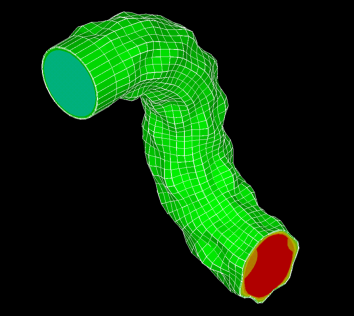
Figure 1 illustrates piping shell modes that are excited by acoustic-induced energy. Shell mode vibration causes small-bore piping to vibrate.
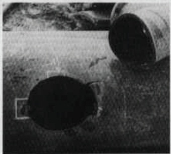
Unless controlled, AIV results in catastrophic piping failures (Figure 2).
The internal acoustic energy can also create external noise that affects operator safety (hearing loss).
 |
 |
|
Figure 1. Example of Piping Shell Mode due to AIV on piping |
Figure 2. Example of AIV piping failure. Source: Chemical and Process Technology 2009 |
2 Common Problem Areas
AIV occurs in a compressible flow stream such as gas or two phase piping systems.
The AIV study is typically performed for:
- Relief valves
- Blowdown valves
- Restrictive orifice plates
- Pressure reducing valves
- Recycling valves
- Control valves
- High flow rate piping
- Concern over external noise levels
Small-bore connections, also called branch attachments, such as welded supports are most at risk. The broadband excitation causes the locations to be resonant, resulting in cracking and fatigue failure.
AIV fatigue failure may occur in a very short period of time (minutes to hours).
3 Wood's Design Approach
Sound Power Level (PWL) refers to the acoustic energy generated by flow through a pressure reducing valve or device. The Acoustic-Induced Vibration Study (AIV design study) calculates the PWL and determines if the piping system is sufficiently strong to resist AIV fatigue. If necessary, changes are made to either the PWL or the piping system.
For a new project, the Engineering Company (EC) or Owner asks Wood to:
- Evaluate the piping system;
- Identify AIV sources and high risk areas; and
- Recommend modifications to the piping system, valves or other solutions to reduce dynamic stress levels.
There are two approaches for evaluating AIV:
- Eisinger or ‘D/t’ Method. This is approach is used to check for piping against acoustic fatigue by comparing the Diameter/Thickness ratio to empirical design limits. The design limits are a function of the PWL as established by Eisinger, Carucci & Mueller, and NORSOK Standard.
- Energy Institute Guidelines (2008). This method checks locations such as branches and welded attachments. The PWL is calculated in a similar manner to the D/t method, but there are some differences in how the fatigue limit is derived.
Wood can meet whichever of the above two approaches the customer prefers. Specialized software is used to improve the quality and efficiency of the analysis, ensuring the project is completed quickly and on budget.
For new systems such as Centrifugal Compressor Systems customers often conduct both the Acoustic-Induced Vibration (AIV) Study and the Flow-Induced Vibration (FIV) Study to ensure that both excitation sources are properly addressed.
If you are involved in the design or operation of high pressure systems, contact Wood for application support relating to AIV and other vibration issues.
4 Wood's Field Services
Contact Wood should you suspect problems in your piping system due to AIV. Our field engineers can provide onsite support to assist with measuring and resolving piping vibration issues.
 |
| Figures illustrate examples of shell mode piping vibration (longitudinal and circumference) |
5 Related Information
- Technical paper: AIV and FIV in Pipelines, Plants, and Facilities (PDF)
- Primer - Piping Vibration INtegrity (PDF)
- Vibration and Pulsation Analysis and Solutions (pdf)
- Specification for ordering an AIV Study (pdf)
- Contact VDN for case study examples or training seminars
6 Related Services
- Acoustic Fatigue Assessment
- Piping VibraTion and Integrity Assessment
- Flow-Induced Vibration (FIV) Analysis
- Surge Control Dynamic Analysis for Centrifugal Compressor Systems
- Energy Institute Guideline (2008) Avoidance of vibration induced fatigue failure in process pipework (AVIFF)
- Pipe stress analysis
- Fuel Gas Compressor Piping Transient Analysis
- Flow-Induced Turbulence (FIT) Analysis
7 Keywords
Acoustic-Induced Excitations
More Info
Free webinar
Learn how to select and design vibration control solutions that work – using real-world data and case studies. Register now


